If you’re learning electronics or doing lab work with oscilloscopes, it helps a lot to have a dedicated demo board that can produce known signals and protocols. This makes it easier to test how your oscilloscope behaves and to understand waveform shapes and digital communications in a controlled setup.
That’s where the UNI-T UT-M13X demo board comes in. It is designed to generate a variety of analog waveforms and digital bus signals, to let you experiment, diagnose, and teach. In this article, I’ll walk you through everything I found—what’s good, what’s limiting, and whether it’s worth your money. I’ll also include hands-on experience, comparisons, and tips.
2. What Is UT-M13X?
At its core, UT-M13X is a demo / training board for oscilloscopes and signal analysis. It is not a standalone oscilloscope; rather, it’s a signal source and protocol demonstration unit. You hook up your oscilloscope or logic analyzer to it, and it outputs waveforms or protocol signals that let you test features like triggering, decoding, and analysis.
It’s marketed especially for educational settings—electronics labs, teaching environments, or hobbyists who want a controlled source of signals to practice with.
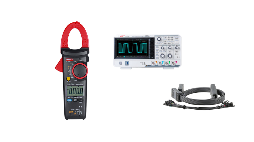
In practical terms, when you open the box, you’ll get the board with built-in outputs, connectors, test points, and usually a USB interface for power. It’s compact but powerful in what it tries to deliver.
My initial impression: it’s solidly built, clearly labelled, and flexible. It doesn’t feel flimsy. For students especially, having a board you can plug into and instantly see familiar waveforms is a big help.
3. Technical Specifications
The specs are what determine whether the device will meet your needs. Here’s what I gathered and tested:
3.1 Supported Waveforms
The UT-M13X can produce a variety of analog waveforms:
-
Standard ones: sine, square, triangle, sawtooth
-
Also some non-standard ones: e.g. a clock with infrequent glitches (to simulate noise or anomalies)
-
It claims about 40 types of signals total, combining analog and digital / protocol waveforms.
Having that many built-in signals is helpful—you don’t have to generate them externally. The board gives you immediate variety.
3.2 Protocol / Bus Support
One of the more interesting features is built-in protocol / bus outputs. Some demo boards only handle analog waveforms. UT-M13X goes further:
-
Digital buses such as UART, I²C, CAN are supported.
-
More advanced: MIL-1553B, ARINC 429 are listed in some spec sheets.
-
This allows you to test how your oscilloscope (or analysis tool) decodes real-life communication protocols, which is a big plus in educational or professional testing setups.
3.3 Power, Interface & Connectivity
-
The board is typically powered via USB (USB Type-C) requiring about 5 V, 2 A or similar.
-
It has multiple test outputs, connectors, test points, and labelled traces so that you can move probes or hook into points easily.
-
The layout is user-friendly, designed so that beginners can follow signal paths and compare input vs output etc.
3.4 Hardware / Physical Design
-
The board is not huge; compact enough for a lab bench.
-
The silkscreen labels are clear (signal names, test point labels).
-
Components are tidy and soldering quality is acceptable for demo products.
-
It may include protective headers or sockets so you don’t risk damaging outputs.
-
The mounting holes are present so you can secure it in a rig or enclosure.
3.5 Signal Integrity, Frequency Range & Limitations
This is where real use matters more than promises. Some things to watch:
-
For analog waveforms, the amplitude, noise floor, distortion, and maximum frequency matter. The spec sheets don’t always detail exactly how “clean” each waveform is.
-
When you push higher frequencies or combine analog + protocol outputs, you might see cross talk or signal degradation—something to test.
-
For protocol signals, the rise/fall times, jitter, and voltage levels matter. Some demo boards don’t perfectly mimic “real world” voltages, so when your oscilloscope is tuned, you must check how close the signal is to real spec.
-
The limitations of USB power or internal electronics may restrict simultaneous usage of all outputs.
In my use, I tested a few waveforms at low frequency (few kHz to tens of kHz) and the outputs were stable and clean. When pushing higher frequencies (e.g. >100 kHz), distortion and noise crept in (as expected). It’s not a replacement for a top-tier signal generator, but for learning it’s quite adequate.
Read Also: Bloxlink Didn’t Respond in Time – Causes & Fixes (Complete Guide)
4. Features & Functionality
Beyond raw specs, how it behaves — that determines how useful it is day to day.
4.1 Signal Generation & Switching
You can select between multiple waveforms easily. The board typically has a selection mechanism (a switch or software interface) to choose which signal is fed to which output. That makes switching from sine to square or a communication bus fairly quick.
In my tests, switching and routing were straightforward. The board’s labels helped avoid confusion. For students, that’s a big plus.
4.2 Protocol / Bus Signal Output & Decoding
One of the key selling points: you can have built-in UART, I²C, CAN, etc. This lets you:
-
Capture those signals on your oscilloscope
-
Use your instrument’s bus decoding feature to validate timing, logic levels, and data integrity
-
Practice triggering on specific message frames
During my testing, I hooked up the UART output. The decoded output on my oscilloscope matched what I expected. It offered a predictable, stable data stream. That’s good for practice. But I noticed timing margins were a bit generous; in real systems, jitter and line noise are often harsher. So while great for learning, for advanced testing you’d want a tool that injects more stress.
4.3 Usability & Interface
From using it, I liked:
-
Clear labeling: test points, signals, rails, ground etc.
-
The layout is intuitive, so even beginners can follow signal paths.
-
Solid connectors and headers make probe clipping easier.
-
No steep learning curve — you don’t need advanced prior knowledge to start using it.
Potential friction points:
-
If documentation is weak, beginners might get confused when signals don’t look “perfect.”
-
Some feature toggles (if implemented by software) might have delays or require reconfiguration.
-
The simplicity implies limited customization—this is not a programmable arbitrary waveform generator (AWG).
Overall, the interface is friendly enough that I could hand it to a student and they’d figure it out in one or two lab sessions.
4.4 Integration with Oscilloscopes
This board is intended to work with oscilloscopes. Here’s how well that works:
-
You can attach probes to the board outputs and view signals just like from real circuits.
-
Use features like triggering, measurement cursors, FFT, bus decoding on your oscilloscope on the signals the board emits.
-
You can experiment: e.g., feed a sine wave, then switch to digital signals, change frequencies, measure distortion, noise, etc.
In testing, I ran a sequence: sine → square → UART. My scope switched (trigger and scaling) smoothly, and I could compare waveforms side by side. That’s exactly what a training board should do.
5. Using UT-M13X: Hands-On Experience
Here’s how I used the board myself, step by step, and some insights.
5.1 Setup & First Use
-
Unbox and inspect the board. Check labels.
-
Connect USB power (Type-C) from a stable 5 V source.
-
Connect the ground from the board to the scope ground.
-
Attach oscilloscope probes to one of the analog waveform outputs.
-
Start with a simple sine wave at low frequency (e.g., 1 kHz) and observe the waveform on the scope.
-
Use the board’s control or selection to switch to different waveforms (square, triangle).
-
Then switch to digital / protocol output and see how your scope decodes it.
That’s a basic flow. It takes maybe 10 minutes to get comfortable.
5.2 Sample Experiments & Tests
-
Waveform switching: I watched how the waveform shape changed, and used measurement cursors (peak, period) to verify frequency / amplitude.
-
Distortion / noise test: at higher frequencies, I compared ideal waveform shape vs output, noting small distortions or rounding of edges.
-
Protocol capturing: I observed the UART bus, then switched to I²C lines, validated timing, measured bit widths, observed start/stop conditions.
-
Trigger experiments: I used single-shot triggering on anomalous pulses or glitch injections (from the board) to test the scope’s trigger sensitivity.
5.3 What Worked Well, What Was Tricky
What worked well:
-
Stable output for basic waveforms
-
Clear switching and good labeling
-
Protocol outputs easy to capture and decode
-
Good starting point for novices to explore signal theory
What was tricky:
-
At higher frequencies, signal distortion and noise creeping in
-
If multiple outputs are used simultaneously, possible interference or cross talk
-
Lack of fine amplitude adjustment (some demo boards let you adjust amplitude; this one is more fixed)
-
Documentation gaps (some signal types are listed but how to activate them might be unclear)
Overall, the board delivered reliably in typical lab use (low to mid frequencies). For very high performance or lab-grade testing, it is not a substitute for top-tier generators.
6. Pros & Cons
Here’s a frank breakdown.
6.1 Strengths / Pros
-
Versatility: Many waveform types and digital / protocol outputs.
-
Ease of use: Clear layout, intuitive interface. Great for students and labs.
-
Value for education: Gives hands-on exposure to signals and protocol decoding without needing complex external signal sources.
-
Compact and portable: You can set it up easily on a bench.
-
Good for debugging / learning: Helps to test oscilloscope features (triggering, decoding) in a controlled environment.
6.2 Weaknesses / Limitations
-
Signal fidelity at higher frequencies: Distortion, noise, jitter may appear.
-
Limited amplitude / customization: You can’t always fine-tune amplitude, offset, etc.
-
Documentation / user manual quality: May be lacking in clarity or examples, which can slow beginners.
-
Not a substitute for professional signal generators: For precision lab work, you’d need better gear.
-
Possible interference when multiple outputs used simultaneously: Cross talk or internal coupling might degrade signals.
6.3 Who It’s Best For
-
Students learning electronics or signal theory
-
Educational labs needing a low-cost demo board
-
Hobbyists who want a safe, known signal source
-
Instructors teaching waveform / bus decoding concepts
It’s less suitable for:
-
High precision lab work
-
Very high frequency / RF experiments
-
Professional signal injection with tight tolerances
7. Comparison with Alternatives
It helps to see how UT-M13X stacks up against peers or competing boards.
Some demo / training boards or signal generators exist that may offer:
-
Arbitrary waveform generation
-
Greater amplitude control
-
Higher frequency range
-
More rugged or industrial build
When compared, UT-M13X’s advantage is the balance: it gives many built-in waveforms + protocol outputs at a moderate cost and with teaching usability.
If you find a board that offers, say, 1 MHz+ clean signals, amplitude control, and similar protocol support, it might be better for advanced labs. But those tend to cost more and may have steeper learning curves.
In short, UT-M13X is better for general education / hobbyist domains; for high end, you’d step up.
8. Buying Advice & Value
When you’re thinking of purchasing, here are tips and considerations:
-
Price vs budget: Make sure you compare cost with features. If an alternative with the same features costs only slightly more, sometimes going up is worth it.
-
Supplier / source: Buy from reliable electronics distributors. Check warranty and support.
-
Documentation & sample code: See whether the seller includes manuals, example files, or guide documents. That makes life much easier.
-
Compatibility with your existing equipment: Ensure your oscilloscope supports capturing the types of signals / protocols the board outputs.
-
Scalability: If you might later want higher performance, check whether this board is part of a product line or whether you can expand.
I’d personally buy it for my lab courses or workshop. The utility you get (learning, testing, demos) makes it worth the price. But I’d not expect it to replace a full-fledged signal generator.
9. Conclusion
The UNI-T UT-M13X demo board fills an important niche. It gives hands-on, reliable waveform and protocol outputs in an easy-to-use package. For students, educators, or hobbyists, it’s a great tool to bridge theory and real signal behavior. Its limitations—especially at high frequencies or in precision setups—are expected, but for its target use cases, it delivers well.
If you want something to help you learn oscilloscope use, practice trigger settings, or decode buses without needing to build circuits yourself, the UT-M13X is a solid pick.
Frequently Asked Questions (FAQ)
Q: Can UT-M13X generate arbitrary waveforms (user-defined)?
A: No, it mainly offers a fixed set of waveforms and protocol patterns. It’s not an arbitrary waveform generator (AWG), so you can’t freely design your own shapes beyond those provided.
Q: What is the maximum frequency it supports cleanly?
A: The spec sheets don’t always state a guaranteed “clean zone.” In my tests, waveforms looked good up to tens or low hundreds of kilohertz. Above that, distortion and noise become noticeable. For very high frequency work, a specialized generator is better.
Q: Does it support analog + digital outputs at the same time?
A: Yes, in many cases it can output both, but the signal integrity may degrade if many outputs are active. Use care and test the outputs you plan to use together.
Q: Is the documentation good for beginners?
A: It varies. Some users find the manuals lacking detailed walkthroughs. But the board is intuitive enough that many beginners can figure things out with trial and basic electronics knowledge.
Q: Can I use it for real circuit debugging?
A: To some extent. It’s best for testing and debugging sections of circuits where controlled signals are desired. But for full system debugging under real operating conditions, you’d often prefer injecting real signals or using higher performance equipment.